
You are using an out of date browser. It may not display this or other websites correctly.
You should upgrade or use an alternative browser.
You should upgrade or use an alternative browser.
Band apply
- Thread starter VIN7
- Start date
Area where half circle/ half moon is on left side raised rib..
http://www.sonnax.com/system/announcement/S043961.pdf
Or http://www.sonnax.com/product-lines/high-performance-transmission/parts/1994
http://www.sonnax.com/system/announcement/S043961.pdf
Or http://www.sonnax.com/product-lines/high-performance-transmission/parts/1994
It hits the side of the raised section.
Yes it can create a dent, as long as it doesn't push a hole through the contact area and the Band to Pin clearance is correct it should be fine.
May be necessary to use a Screwdriver to help align/position the Band if it's needed. The Pan would have to be off tho'. There's also Info on here about setting clearance Specs etc.. if you do a search.
Air test locations with Pan & Vbody off >> http://www.sonnax.com/system/instructions/K65703-IN.pdf
TexasT
Texas, Where are you from
- Joined
- Sep 10, 2002
The air test involves you applying air to the piston. You should be able to turn the out put shaft without the air. Then when you apply the air you won't be able to turn it. I put a yoke on the output to make turning it easier. I also use the yoke to locate the output when I assemble.
Posted from the TurboBuick.Com mobile app
Posted from the TurboBuick.Com mobile app


TexasT
Texas, Where are you from
- Joined
- Sep 10, 2002
Might have. I cant really see it too good but it looks like it might have punched a hole in it.
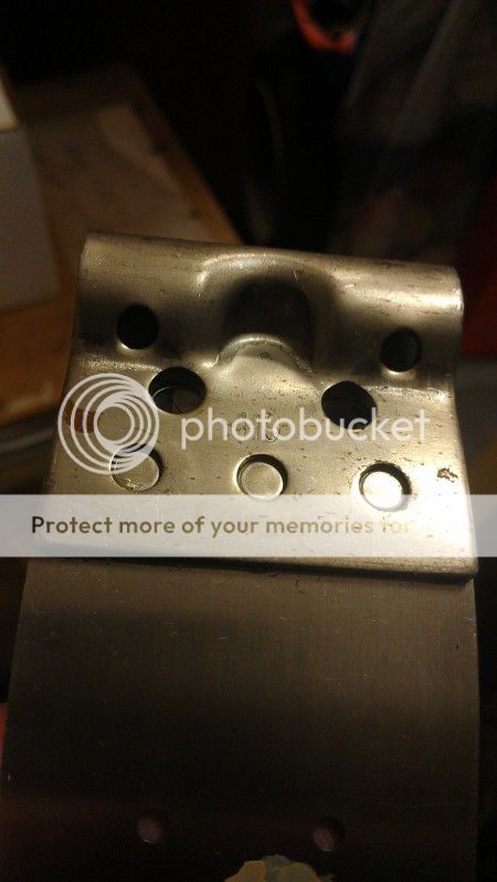
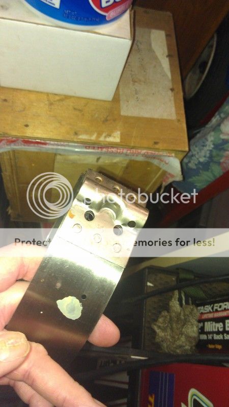
This is a new carbon band. It has the indention so I think they all do. You can see the heat treat on the pin end.
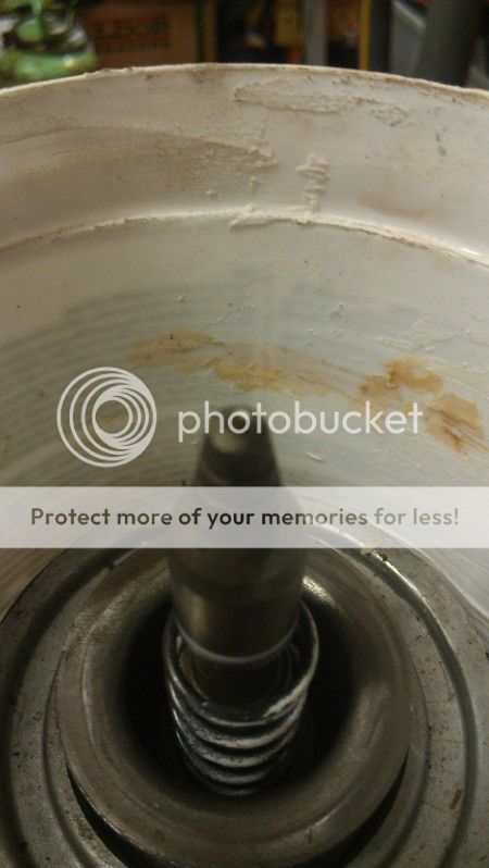
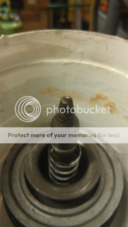
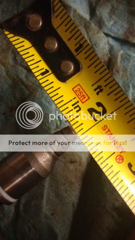
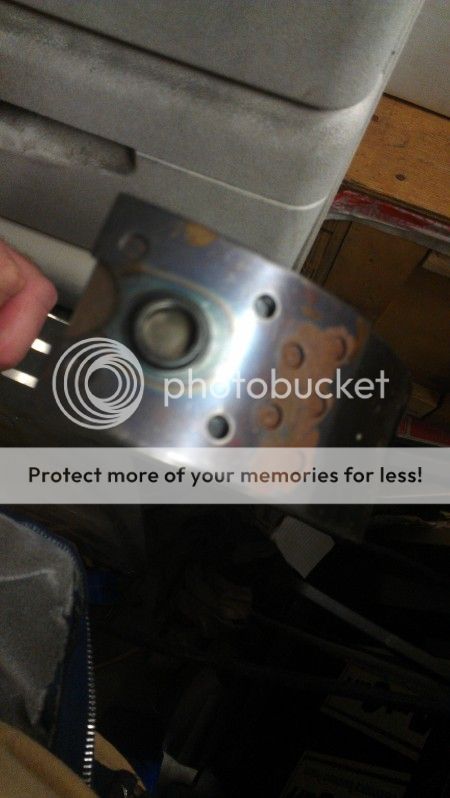
This is the pin that came out when I swapped in the new Sonnax setup.


This is a new carbon band. It has the indention so I think they all do. You can see the heat treat on the pin end.


This is the pin that came out when I swapped in the new Sonnax setup.
Thanks Rich, now I have a very clear understanding how they all fit together. I can't actually see into my servo area because of the exhaust so I've been sticking my phone up in that area. I've got about an extra .15" movement on my servo cover above spec, pretty sure that it punctured that thin area of the band. Seems like they could have engineered a little more material in that area, or made the pin less pointy.
TexasT
Texas, Where are you from
- Joined
- Sep 10, 2002
The sonnax instructions indicate that the pin grinding should include rounding over the pin end to fit a half washer. Not sure what yours looks like but if it was sharp it could have been a problem.
David Husek indicated in one of his posts that the clearance in the servo differed with which band material was used and that he had never set one up to a clearance. He does them by feel. He also indicated that clearance is pretty tight. When i did mine we put it in without seals n springs and got it to .0606 between the cover and retaining ring with a feeler gauge. Then squirted air in to clamp the band. Seemed to work but it is still on the stand and not in the car yet.
David Husek indicated in one of his posts that the clearance in the servo differed with which band material was used and that he had never set one up to a clearance. He does them by feel. He also indicated that clearance is pretty tight. When i did mine we put it in without seals n springs and got it to .0606 between the cover and retaining ring with a feeler gauge. Then squirted air in to clamp the band. Seemed to work but it is still on the stand and not in the car yet.
stovebolt 34
Member
- Joined
- Mar 9, 2012
Great pix Tex . you going back with a stock width band or the wider one ? Carbon or ?
TexasT
Texas, Where are you from
- Joined
- Sep 10, 2002
Went with the stock width carbon band. I didn't have a lathe or take it some where to have it cut so I thought it best to do stock width. I did "rough" it up in a cross hatch pattern as indicated in the ck book. I did the steels that way too with some sandpaper.
Sent from my HTC PH39100 using TurboBuick Mobile mobile app
Sent from my HTC PH39100 using TurboBuick Mobile mobile app
I have a question regarding what you said about using the yoke to set the output shaft. I was reading the ASTG manual and it says to use some tool to adjust the output shaft location and to use the tool to check some of the clearances. I made a fixture with a bolt to set it into the output shaft to hold it tight. The manual mentions a sleeve for the output shaft to adjust the depth, what would this sleeve do versus just having a bolt hold the shaft up? The manual also says to adjust the shaft further in until the white mark on the sleeve is just inside the housing. Thanks
paul
paul
Your method will work fine. I use a piece of wood bolted to the case and a screw to hold the shaft. I can put it exactly where I need it to be.I have a question regarding what you said about using the yoke to set the output shaft. I was reading the ASTG manual and it says to use some tool to adjust the output shaft location and to use the tool to check some of the clearances. I made a fixture with a bolt to set it into the output shaft to hold it tight. The manual mentions a sleeve for the output shaft to adjust the depth, what would this sleeve do versus just having a bolt hold the shaft up? The manual also says to adjust the shaft further in until the white mark on the sleeve is just inside the housing. Thanks
paul
TexasT
Texas, Where are you from
- Joined
- Sep 10, 2002
I bought what I thought was the fixture years ago. Unfortunately I couldn't get it to work so I guess it is for a different trans. I read about using the yoke so I did. I adjusted it with a coat hanger to get the output where the parking pawl would engage. I'll look for pix.
Sent from my HTC PH39100 using TurboBuick Mobile mobile app
Sent from my HTC PH39100 using TurboBuick Mobile mobile app
I'm not sure I should confess this in a public forum, but I held the output shaft in place with gorilla tape. Had the correct trans fixture hanging it vertical, so just looped it under and stuck it to both sides of the case and adjusted it till the park pawl was centered. Made sure it didnt move and that all the clutches were engaged, etc and used a little extra caution until the rear section was fully assembled. I'd do it again that way too.
TexasT
Texas, Where are you from
- Joined
- Sep 10, 2002
I see nothing wrong with gorilla tape, or any method that gets the output shaft were ot needs to be.
I can see if you run a shop and build many but most of us will build a few. Unless you can pick up the fancy fixtures cheap it doesn't make much sense when there are cheap and free ways.
Sent from my HTC PH39100 using TurboBuick Mobile mobile app
I can see if you run a shop and build many but most of us will build a few. Unless you can pick up the fancy fixtures cheap it doesn't make much sense when there are cheap and free ways.
Sent from my HTC PH39100 using TurboBuick Mobile mobile app
Similar threads
- Replies
- 72
- Views
- 6K