I built my own flowbench and it works.

Pablo

Active Member
Joined
Sep 12, 2004
Turbofabricator mentioned Gofastnews.com in one of his replies to my head porting questions. Turns out David Vizard has been posting a series of head porting articles on that site. A few of them deal with building your own home flow bench.
When I saw the simple DIY flowbench he detailed in the first flowbench article I just had to build it. Here is the article Porting School #2 - Super Cheap Flow Bench - GoFastNews.com - All Racing News All the Time!


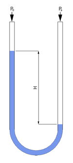
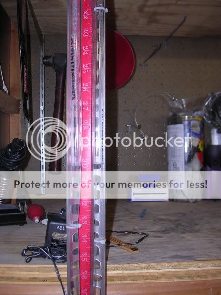
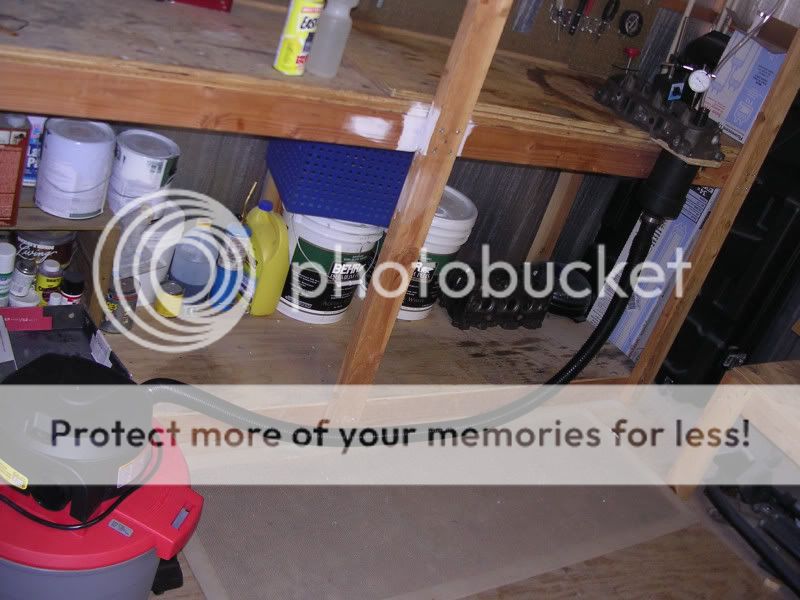
So off I went to the hardware store. I picked up a shop vac, I needed one anyway, and then I purchased some clear 3/8ths hose and a piece of angle something or other that I dont have a good name for. I made a manometer with this, some zip ties, and a measuring tape.

flowbench4.jpg


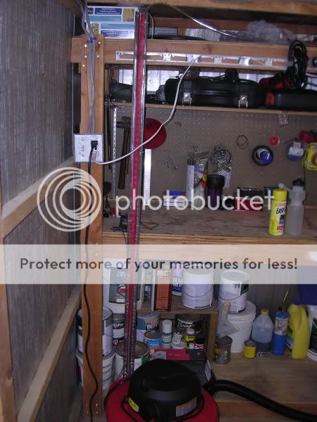
It's about 60 inches long so I made the midway point at 30 inches

flowbench6.jpg


I then had to fab up an adapter and bore plate for the head. I did this out of wood, I then epoxied in some 4" schedule 40 pvc pipe into this thing. Yes the bore is 4" which is a little bigger than the 3.8 bore but for what I'm doing this is close enough. I also used the epoxy to form some threads that I tapped directly into the wood since there wasnt really any space for a nut. This actually works really well.

flowbench2.jpg


flowbench1.jpg


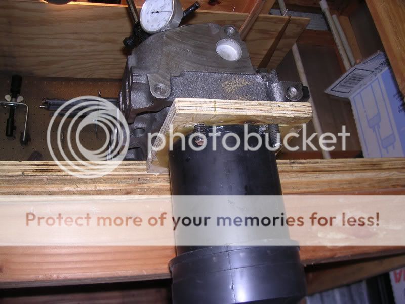
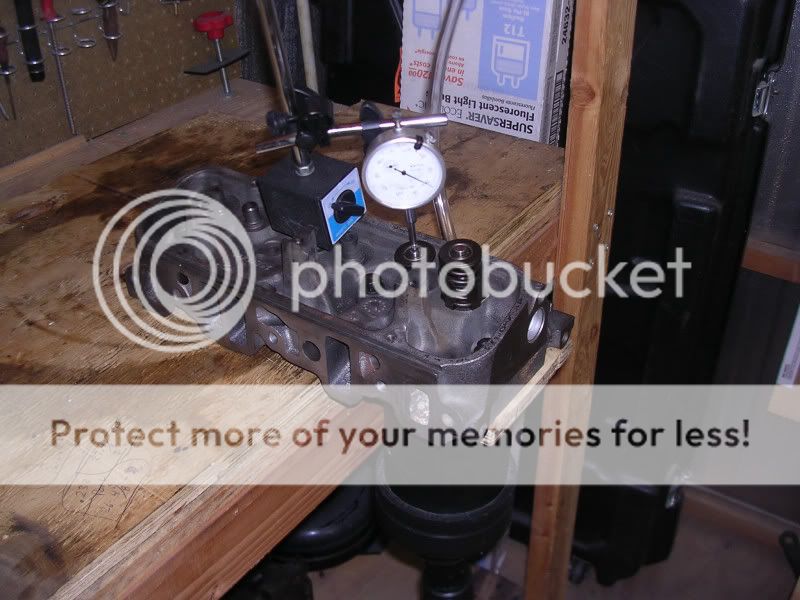
The rubber coupling at the bottom is just a 4" to.. about a 2" opening.. i cant remember exactly. PVC pipe and couplers have a completely moronic way of being measured that has no bearing on its actual size. This was probably the most expensive part of the flowbench at 14 dollars (aside from the shop vac and dial micrometer)

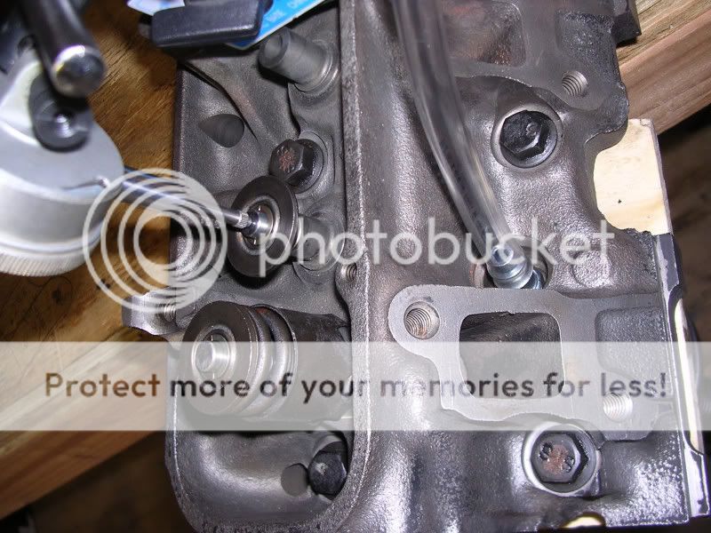
Connected the manometer to the spark plug hole with an air tool fitting (I just hand tighten it with teflon tape. It doesn't leak... I'll get a fitting from a compression tester or some such thing later)

flowbench3.jpg


and then I just let it rip

flowbench5.jpg


I compared a stock head to a head I've been porting. To my dismay, at .233 lift, the stock head flowed like 1/32nd of an inch more than my ported head.

I then upped the lift to .425 and the difference between the stock head and the ported head became very pronounced. The ported head flowed a full inch of water more than the stock head. That's a lot considering that there was only about 2.5 inches of vacuum in total. That's like a 33% improvement over stock

At .655 lift (just for kicks) the stock head was still an inch behind. The difference in flow from .655 from .425 wasn't a lot. Only about 1/8th inch.

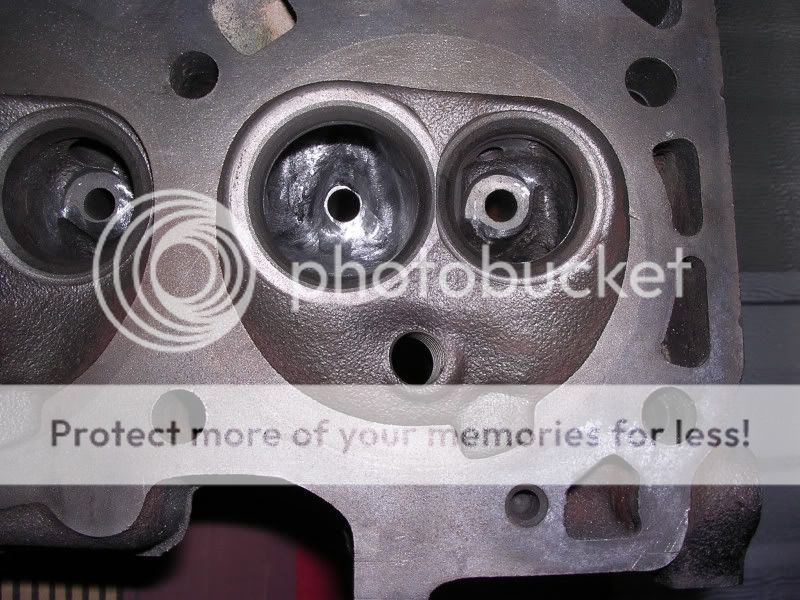
Here are a couple of picts of the ported head in question. I'm still not done with it. I need to do some smoothing and chamber work. BTW, nothing at all has been done to the actual port entry of the head aside from removing the hump around the head bolt hole. No gasket matching of any kind or anything like that. I'd say 85% of my grinding was in the bowl, valve guide area

flowhead.jpg


flowbench7.jpg


I'm gonna have to build or buy a more precise manometer for the higher lift readings. There isn't as much resolution as I would like. At low lift there is a ton though.

I'm pretty happy with the set up. I just need to figure out a way to open the valve more precisely/ easily. I was thinking two threaded sleeves under the keeper that I screw to raise and lower the valve. Any one have any better ideas?
 
BTW

I know I'm going to have to figure out a way to increase the pressure drop, 2.5" of h20 is not enough to give me an accurate flow pattern in the port.

This is just preliminary work.

It does look like for the higher lift ranges I might need a more powerful shop vac :(
 
That looks like a lot of fun. You'll be learning the flow numbers to all kinds of crazy crap now!;)
 
Yeah, I'm pretty excited

I also figured out that I'm a dumbass and have been reading the manometer incorrectly. Turns out its the difference between the two columns of water and not the distance from the center. So essentially my numbers should be double which is good enough to get results that mean something.
 
You could use a hight mic under the retainer for your hight adjustments. I just fond one through summit and they're about $50 but it's a good inexpensive tool for your tool box.
 
I have seen one similiar. You will need a much larger vacuum to get to 28" of h2o. There are also flow meters avaiable that can read cfm so you get an air flow reading.
 
Angle the manometer tube to expand the scale. If it is at 45 degrees then a ruler running parallel to the tube will show 1.414" for every 1" of height difference. Angle it at 30 degrees (a very shallow angle, almost horizontal) and the ruler along the tube shows 2" for every 1" of height. If one end of the u tube goes to your plug adapter and the other end is open to the air, then the distance on one side from center is the pressure or vacuum, not the distance between the up side and the down side. If you measure that I think you will get twice the accuracy but you need to divide the answer by 2 to get the true pressure.

You don't have anything on the inlets to the intake ports to smooth the flow, so you won't get a real picture of the complete engine. Ideally, bolt on an intake manifold and then you can have some confident that any changes you see are due to your porting deep in the ports and not an artifact of the inlet air. The local porting shop has wooden adaptors with a horn shape carved from a 2x4. The bottom of the horn matches the port and the top of the horn is about twice the width and height, with a smooth radius as you go down the hole. That way the exact size and sharpness of the port edge won't matter.

Also, I suggest going to Speed Talk: Interviews - Racing Books - Racing Forum and reading in the archives of the general engine tech forum. Lots of great head porting info there, by some names like Darrin Morgan, chief porter for ReherMorrison, and others.

Good work building the bench and doing some quantitative comparisons, instead of just eyeballing it.


Thanks for the tip on putting the manometer at an angle.

I have seen the wooden inlets people use to radius the port entry. I was thinking about making one too. One thing I noticed though is that by moving my finger around the opening I saw very little changes in flow so it would seem like the port entry isn't affecting the flow numbers a ton. Of course that's not really that scientific of a test :)

As for the height measurement.. reason I thought it was the difference in height was this wiki article Pressure measurement - Wikipedia, the free encyclopedia

150px-Utube.PNG
"The difference in fluid height in a liquid column manometer is proportional to the pressure difference. H=\frac{P_a-P_o}{g \rho}" Maybe I'm reading it wrong.
It would also jive with the measurements that Vizard gives in his articles where his 2.5 hp vac hit about 220 cfm at around 4-5 inches. My 3.5 hp vac is hitting about 5 inches (height difference) at .5 lift. :confused: It would suck if that was really 2.5 inches.. That would mean my vac was weaker than his.


Dusty,

Theres actually no need to hold 28" of h2o with this type of setup. The vizard articles go into making a calibration plate that allows you to convert your test pressures into cfm #s at 28". I'm just happy I'm able to do a comparison between ports right now.
 
So I ran some numbers... I found that my ported intake port flowed about 16% more than the stock one at .4 lift

Using the flow numbers of a stock head at 28" and .4 lift (151 cfm is one example i found) that would mean that my porting job has netted me about 175 cfm at .4" That still sucks :frown:

But its better... and yes, that's a pretty loose estimation as to what they actually are flowing at 28"
 
To get an actual CFM number use a MAF and put it in the suction line. Since it is only one cylinder of air can even use a small one from a V6 or TPI car. The '86 - '89 TPI MAFs are a voltage output (not freq), so it makes it easier to read.

You can also use modeling clay to provide a radiused entry to the port.

Nifty setup.

RemoveBeforeFlight
 
Is there a chart that will show actual CFM vs. voltage of any of the MAF sensors? That would make life easier. I guess you could use CFM through known orifices and the amount of water lift to determine the calibration curve if you had to.
 
Sigh, you are right, Pablo. I'm too used to explaining manometers with a fixed height pool of mercury; in this case the pool level also drops as the column rises. I also forgot to include the formula for the scale expansion: 1/sin(angle from horizontal). So at 45 degrees from horizontal the sin(45) is .707 and 1/.707=1.414, and one inch of vertical height will equal 1.414 inches along the inclined surface. I saw this on a SuperFlow bench, I didn't invent it :). I think they used about 30-45 degrees. Oh, the whole U does not need to be tilted, only whatever region you want to expand. In this case I think maybe 20 inches around the middle so you can, say, tell 5.5 from 5.7" better. I think you get much greater differences in vacuum for small differences in flow up at the 100" area, right, so that part doesn't need the tilt?
 
for home porting stuff, you might pick up the book "Practical Gas Flow", by John Dalton (altohugh Amazon.com lists the author as R.M. Clarke for some reason. The picture they show clearly has John Dalton as the author.). Amazon has it for $15. He talks about making a flow bench, but then goes on to home porting techniques. Basically he builds a dummy head from plaster of paris, does a bunch of testing on that, then we he gets something he's happy with he transfers those changes over to the actual head. He's got some good how-tos and ideas in there. Very worthwhile for the home handyman I thought.

John
 
Excellent Ideas and suggestions guys.

The Vizard articles go into fabbing up a calibration plate with specific orifice sizes and radius entries so that you can convert your results to legitimate cfm numbers at 28". I might look into that later.

As an update, I went and exchanged the puny 3.5 hp vac for the most powerful vac they had at home depot which is a rigid 6.5 hp monster. It actually was not the most expensive vac either so that worked out well. The new vac pulls crazy vaccum. I was just testing a stock head and at .5 lift the pressure drop was 21 inches and some change which is 4 times what I saw before. The port inlet sounds like a jet engine when I'm doing this. I think I'm going to have to research some sort of radiused port entry for sure now. What I don't get is that I see varying kinds of port entries used on flow benches in pictures. Actually I see some people using them and some people not using them.
What I really need to know is whether or not the changes I make down in the bowl area really care about how the air is way up by the port entrance. I would think it would "clean up" by then. I can def. see how I would want a clean port entrance if I wanted to see the difference porting the port entrance was making though.
 
To get an actual CFM number use a MAF and put it in the suction line. Since it is only one cylinder of air can even use a small one from a V6 or TPI car. The '86 - '89 TPI MAFs are a voltage output (not freq), so it makes it easier to read.

You can also use modeling clay to provide a radiused entry to the port.

Nifty setup.

RemoveBeforeFlight

Yeah, this is a good idea. I've thought of it for a while, it would be simple as a digital volt meter, a PC power supply with the 5V leg to power the MAF. I believe that the later LS1/LT1 MAFs are likewise voltage regulated. If you had a frequency counter you could use the Buick MAFs as well. Some CD4026es would make for a VERY easy display circuit. You would need a clock circuit, nothing an NE555 wouldn't fix or a crystal based setup if you wanted more precision. According to the below link a typical Voltage based MAF of the era is .4-.8v at idle to 4.8-5V at WOT. For the freq ones the range is usually 32-150hz, so you would need a maximum of 4 BCD counters if you wanted a tenths digit.


http://www.wellsmfgcorp.com/pdf/Counterpoint3_2.pdf


ED:if someone is interested, I'll draw out a schematic of a frequency based counter with the above mentioned ICs.
 
To see where the air is going:

Get a thin steel wire (like MIG or piano wire) and glue a piece of thread to the end of it (sewing thread). Can use a bright color to make it easier to see.

Then simply move it around the port and watch the thread. Make up a bunch with different colors and lengths.

To get really fancy make a miniature hot wire MAF probe. Can then measure the air velocity at different points within the port.

Full size MAFs, the stock GN MAF is a low frequency type (32 - 150 Hz). The LT1 and LSx series are high frequency types (1.5 - 12.0 KHz). There is information on the 'net that provides the grams per second airflow vs. the output. Some DVMs report frequency.

RemoveBeforeFlight
 
That book I recommended also talks about using a probe to see where the air is flowing. His method is a little rougher, he just puts a small ball of clay on the end of the wire, and then watches the air flow he's measuring as he moves the probe around. If you move the probe to a dead area where there is no flow the reading doesn't change at all, if you move it to a high flow area where the little ball of clay blocks the flow then you see a big change in air flow. You just move all around the port or runner and see where the air is really moving.

That book also has lots of tips about shapes and whatnot to shoot for. And the Power Source book has some porting templates that might be helpful to you.

I've toyed with the idea of building a flow bench for a long time, but never got around to it (and probably never will). But I figured that if I did, I would try to build a simple little venturi meter to measure the air flow, using the same kind of water filled manometer that you've built. A couple of chopped up funnels and a piece of pcv pipe (smaller than your main air flow pipe), a little epoxy, and voila. I can explain more if you're interested.

Oh yeah, I think to get the right bore size to put under the cylinder head, I think you can start by wrapping some stiff plastic sheet around a piston, and then figure out how to secure it so it keeps the proper shape when you pull the piston out. Then you can really get the shrouding effect of the cylinder wall properly modeled.

John
 
If you have a lathe handy, schedule 80 4" pvc pipe is 3.786" ID so you could bore it to 3.800" or just use it at 0.014" undersize to compare to schedule 40 4" pvc, which is probably what you are using now at 3.998" ID. HomeDepot won't have the heavy stuff but a local plumbing supply store will, or you can order 5' from McMaster-Carr.
 
Top