GN1 Roller Rockers

Stock rockers...solid shafts...212/212 flat tappet cam...6 grand all day...zero issues.
 
I prefer higher ratio rockers, as they widen the powerband, and make more power, or can allow slightly less boost. A roller cam makes more power due to faster ramp rate and higher lift, but both of these parameters are improved with higher ratio rockers.
For those who think that it's a waste having a higher lift than the head flow supports, consider this:
The max lift of the cam only occurs for a few degrees of rotation, and on opening, the ports air flow is "chasing" the valves instantaneous lift, and therefor the actual port flow is always less than valve lift suggests.
For the few degrees that the cam is at max lift, the airflow never catches up to the lift. Soooo, we must make the cam lift higher than the max port flow lift to allow the port flow to catch up with the max lift of the cam, otherwise the max port flow will never be achieved in a running engine. I usually run + .060 lift (more with a higher RPM engine) than the port can flow to allow the port flow to actually be the limiting HP factor, not the valve dwell time at max lift.
Also, in a running engine, pushrod flex, rocker arm flex, Hydraulic lifter bleed down, or lash with a mechanical cam, all reduce the actual valve lift! So your heads will never achieve theoretical flow rate or HP with a lift equal to port flow.
TIMINATOR
Timinator,
I agree with you concerning things that reduce valve train lift- one of the most important things is the weight of the components used in your valve which will determine or limit the amount of safe engine RPM under high boost. Setting up the valve train geometry correctly plays a big factor in the reliability of a valve train no matter what expensive rocker arms your using. Also Port flow matching the heads and knowing what each cylinder flow data will also help determine what camshaft need for the combo. Sounds like you have build quiet a few bad ass GN engines- good info you posted my friend.

Haulz A
 
In my experience valvetrain weight is more important in N/A, high RPM engines than our usually lower RPM turbo engines. Although a few on here are really buzzing them!
As far as valvespring pressures go, most newbies tend to ignore the apparent reduction in useful operating rpm limits due to the boost acting on the back of the intake valve, and exhaust back pressure acting on that valve. Exhaust back pressure varies from 1.5 times boost pressure to over 3 times boost pressure!
It's quite a reduction in useable spring pressure.
An LS spring used in a 7200 rpm N/A engine may not function correctly over 5500-6000 rpm in a boosted engine.
To calculate this effect, measure the inside of the intake valve seat, calculate the area, less the stem diameter, and multiply that by boost pressure. Then subtract that from actual seat pressure.
For the exhaust spring, do the same, but for an average build, use double the boost pressure since the exhaust backpressure is always higher.
If you are an anal-type guy like me, measure the actual exhaust back pressure with a bung just before the turbo for your calculations.
This is why you need dual springs as the boost gets up there!
An easy test if you have enough spring pressure is run the car and note where the engine "noses over."
Then drop the boost 8 or 10 lbs. and see if the motor RPMs higher. If so, you need higher pressure springs!
TIMINATOR
 
Or a tighter spark plug gap, or a better ignition, especially on alky or spraying a lot of alky.
TIMINATOR
 
This one of my street builds uses lightweight valvetrain parts, and 1.7 rockers! Buzzy street stroker...
The 6 pak 510 stroker doesn't....
TIMINATOR
 

Attachments

  • Message_1556044415198.jpg
    Message_1556044415198.jpg
    1.3 MB · Views: 67
  • Message_1556044438603.jpg
    Message_1556044438603.jpg
    1.3 MB · Views: 69
  • IMG_20220609_182632.jpg
    IMG_20220609_182632.jpg
    1.1 MB · Views: 70
Ooooopps! The build room is also the politically incorrect room! I didn't notice the background pic! Wife and I have been together for a bit over 2 years, pics have been there longer, and freshened up from time to time. She is fine with them.
If anyone has an issue, I or the moderator can deal with it, no problemo. I am in my 70s, and grew up in an Era where pics and calenders were normal. My clientele is 40s thru 80s, and they like the retro look too! Wife is HOT, so she's not intimidated.
 

Attachments

  • 20211011_065846.jpg
    20211011_065846.jpg
    793.6 KB · Views: 55
NP! The tits in that one pic are obviously fake. and your wife just wonders about your sanity. :ROFLMAO:
I just finished checking a set of injs from that FERD engine, that's dressed exactly as yours is.
 
Sanity? But I haven't had an episode in NINE MINUTES!!!!! The wife embraces my insanity, it makes her seem normal, LOL!
The fake ones are courtesy of an employee, he likes that stuff. YUK!
He embraces the David Spade attitude: "fake looking real ones..
Or real looking fake ones."
I, on the other hand, am an:
"ANY size real ones are better than
Any size fake ones" guy.
Any way, back to the subject at hand, I do some testing and advising for the guys that made that injection system.
The first batch of them didn't idle, transition, or run well, and I traced it to no holes connecting the under manifold plenum to the runners! The MAP, IAT, and IAC are threaded into the plenum, but there was no connection to the runners!
I drilled connecting passages and thought it would be fine, NOT..... Then all I needed to do was loosen the throttle blades, reseat them into the throttlebodies, synchronize the 4 of them, and move the IAT sensor to one of the rear stacks. You may want to check all of that, as they and I don't know how many of the early ones were sold that were bad. Once in a while you can find an early setup that someone is dumping cheap because they couldn't make run, and fix it.
TIMINATOR
 
Latest ferd: 400" 351 W stroker, alum heads, roller everything, in a 1967 Ranchero.
My business motto: "With cash, all things are possible."
TIMINATOR
 
In my experience valvetrain weight is more important in N/A, high RPM engines than our usually lower RPM turbo engines. Although a few on here are really buzzing them!
As far as valvespring pressures go, most newbies tend to ignore the apparent reduction in useful operating rpm limits due to the boost acting on the back of the intake valve, and exhaust back pressure acting on that valve. Exhaust back pressure varies from 1.5 times boost pressure to over 3 times boost pressure!
It's quite a reduction in useable spring pressure.
An LS spring used in a 7200 rpm N/A engine may not function correctly over 5500-6000 rpm in a boosted engine.
To calculate this effect, measure the inside of the intake valve seat, calculate the area, less the stem diameter, and multiply that by boost pressure. Then subtract that from actual seat pressure.
For the exhaust spring, do the same, but for an average build, use double the boost pressure since the exhaust backpressure is always higher.
If you are an anal-type guy like me, measure the actual exhaust back pressure with a bung just before the turbo for your calculations.
This is why you need dual springs as the boost gets up there!
An easy test if you have enough spring pressure is run the car and note where the engine "noses over."
Then drop the boost 8 or 10 lbs. and see if the motor RPMs higher. If so, you need higher pressure springs!
TIMINATOR
Awesome teck my friend!
Hope guys that have lackluster results with their combos are paying attention 😉
 
I had an ex-customer and kind-of-friend doing a blown (14-71) alcohol street outlaw car a while ago, and he thought magneto ignition was "old school crap" so he did a complete MSD 8 with all the bells and whistles. It started easily, free revved cleanly, sounded great on the burn out, crispy on the hop and stage, launched clean and mean, went out hard to about 200 feet, started breaking up, and immediatly shut off, right about the time the last stage of the clutch locked up. I tried to tell him MSD has a sharp rise time, high voltage, short duration spark, and when the motor was really loaded, the MSD did not have as high AMPERAGE and a long enough duration spark to light the charge.
He played with boost, fuel curve, timing, and everything he could think of for 2 months. His partner was one of my ex employees, so I loaned him a mag, my ex employee installed it without telling him, and the car ran like it should. Instead of the owner being happy, he never spoke to me again, and I never got the mag back. Something to keep in mind.
I think some of the really fast alky turbo cars are or will experience this. Or mebbie MSD has come up with something newer for this app. This occurred about 10 years ago. It was over 500 inch, 1471 blown, multi stage fuel car clutch deal like a blown alky funny car.
Just mentioned this in case it may be relevent.
TIMINATOR
 
A more compact combustion chamber, automatic trans,V-6, small tire buick, may not get to the same cylinder loading of a blown alky funny, but then again, it might....
TIMINATOR
 
Any way, back to the subject at hand, I do some testing and advising for the guys that made that injection system.
The first batch of them didn't idle, transition, or run well, and I traced it to no holes connecting the under manifold plenum to the runners! The MAP, IAT, and IAC are threaded into the plenum, but there was no connection to the runners!
I drilled connecting passages and thought it would be fine, NOT..... Then all I needed to do was loosen the throttle blades, reseat them into the throttlebodies, synchronize the 4 of them, and move the IAT sensor to one of the rear stacks. You may want to check all of that, as they and I don't know how many of the early ones were sold that were bad. Once in a while you can find an early setup that someone is dumping cheap because they couldn't make run, and fix it.
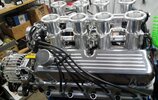
Tim, I think this set up is several yrs old. The customer bought the engine already done and supposedly running.
The guy doing the work mentioned it as being a Borla unit. Is that the guys you work with?
This unit has no IAC. It does have individual air bleeds that have evidently frozen up and cannot be turned.
The engine is also a stroked Windsor 400". The ecm is a new Holley Terminator.
John Kaase has welded a plenum under the intakes he does. That allows for an Iac.
Any info you may want to share is appreciated.
 
A Pro Comp/ Speedmaster setup is what is on this motor. All of theirs have an IAC and a plenum beneath the entire flat surface of the floor plate. Chinese parts pretty much come from the same mfg. Plant there, no matter what American brand is on them.
I was not aware that Borla was vending F.I. units.
I did a beautiful Crower BBC calliope stack injection conversion about 2000 or so. On that one, I connected the runners with -4 lines to an underneath mini plenum with the IAC on it. Then where the normal injectors were, I machined and welded bosses for the electronic injectors. Someone sold adaptors to run a -3 or -4 individual line to each injector. Those all connected to an aluminum distribution block that looked like the stock barrel valve, but also had a hidden TPS. It connected with the original barrel valve linkage too! With that nestled between those 2 1/2" stacks, you really had to look hard to see it was an EFI conversion!
I think it went to Canada or Minnesota. If I find pics, I'll post them!
I have an idea for a 3.8 fabricated manifold that I will build once my car is running too.
I cut my teeth on the old Corvette Crossfire F.I. unit from 1984.
With one of the first Crane Hydraulic roller cams (running solid lifters),headers, a welded and severely ported intake, bored and ported T.B.s, 1.6 RRs, a hollowed out CAT, 3.70 gears I think, and tricks to get the ECU to understand the lower vacuum signal, it ran mid/low 12s reliably on "sticky for the day" street tires.
When returned to the dealer for an unrelated recall, I had to let the Service Mgr. drive it, and he agreed he wouldn't void the warrenty!
Aaah, those were the days....
TIMINATOR
 
Tim, I just got some more info.
This one is a TMZ.
TMZ was bought out by Borla.
This is the 3rd stack I've seen.
1 on a Kaase Boss 9, 1 on an LS3 in a 53 Buick, this one in a 67 Mustang.
The LS/Buick was a Borla as they now cast their name in it.
The Boss made 715/760 on pump gas, and is in a 51 Merc sled. Not bad.
 
This one is in a 1967 Shelby clone Mustang. It came from Pro Comp/Speedmaster, and runs a FAST ECU.
TIMINATOR
 
I have contacts at Speed Master/ Pro Comp. They are the "house" brand for heads, manifolds, rockers, rocker covers, and more at the several top volume retail vendors.
P.S. out of ALL of the brands of aluminum heads and manifolds we sell, they are the ONLY ones we have never had to do a warrenty return on. But we don't use their fasteners only ARP. Just sayin'.
TIMINATOR
 
Top