hot air 84GN
Member
- Joined
- May 7, 2009
Hopefully some of you guys that have done this can offer some insight. After searching and reading post/threads for a week so, I am still not fully convinced on what to do. I am picking up the 25503134 bracket tommorow, an alternator for a 97 Camaro (LT1), and a wiring adapter 85854 (doorman).
I guess I might have to re-clock the housing. Exactly why, I am not sure of. I'm guessing for the wiring connections? And I have read that I will have to remove my v-pulley off of my original alternator and put it on the new alternator since it comes with a serpentine pulley.
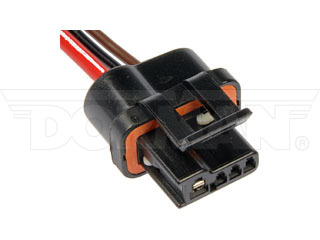
The biggest question I have is about the wiring connnector. My wiring adapter plugs into the alternator (obviously) then has 3 wires. Red, brown, and black. Red for 12 V power. Is that correct? Then the brown wire from the adapter....does that connect to the wire that eventually connects into the coil/module area? And from what I have read, the black wire does not get used? I think.
On my hot air alternator, I had a post that read "batt" and had all of my wires connected to it with ring connectors. One from the positive battery post, one from my hot wire (fuel pump kit), and one that I traced back to the coil/module. On the alternator side of the "coil wire" it is factory brown and it reads: fusible link. Is this right? On my hot air alternator, there are two spade terminals on the top of the alternator. One spade terminal is connnected to the "batt" post as well as the other 3 wires.
Also does the new 140 amp (LT1) alternator have a post for ring terminals? Or does everything connect through the wiring connecter?
If anyone could help me out, it would be much appreciated.
Thank you, so much!
I guess I might have to re-clock the housing. Exactly why, I am not sure of. I'm guessing for the wiring connections? And I have read that I will have to remove my v-pulley off of my original alternator and put it on the new alternator since it comes with a serpentine pulley.
The biggest question I have is about the wiring connnector. My wiring adapter plugs into the alternator (obviously) then has 3 wires. Red, brown, and black. Red for 12 V power. Is that correct? Then the brown wire from the adapter....does that connect to the wire that eventually connects into the coil/module area? And from what I have read, the black wire does not get used? I think.
On my hot air alternator, I had a post that read "batt" and had all of my wires connected to it with ring connectors. One from the positive battery post, one from my hot wire (fuel pump kit), and one that I traced back to the coil/module. On the alternator side of the "coil wire" it is factory brown and it reads: fusible link. Is this right? On my hot air alternator, there are two spade terminals on the top of the alternator. One spade terminal is connnected to the "batt" post as well as the other 3 wires.
Also does the new 140 amp (LT1) alternator have a post for ring terminals? Or does everything connect through the wiring connecter?
If anyone could help me out, it would be much appreciated.
Thank you, so much!
 I am finally starting to get that Ahh-Ha moment!