Home made Ground Kit

"Reaper"

Gone To The Dark Side
Joined
Nov 22, 2007
I am an Electrician and figured if it can work on a house it can do the same for a car.

So I took all the grounds off the back of the passenger side head (6 wires)and soldered them to some black #12 wire about 4" long and heat shrink the solder joints. I took the #12 wire to a 7 hole grounding bar (can be bought form any hardware store) One wire I double up but no big deal. I then took two #10 wires and installed yellow eyelets and put them under the coil pack bracket.Cost was about $6 i had everything but ground bar.If you can't find a seven hole one if its long you can just cut it with a saw.

Here is a pic of the ground bar on the firewall.

MyGN007.jpg


MyGN006.jpg
 
An alternate idea that Arizona GN (Nick) told me is to relocate the bolt/stud used on the lifting eye at the front of the manifold to the rear passenger side hole. The grounds will reach, and the eye's fit over the stud. That is a good idea you have there though, provided the set screws don't vibrate loose.
 
An alternate idea that Arizona GN (Nick) told me is to relocate the bolt/stud used on the lifting eye at the front of the manifold to the rear passenger side hole. The grounds will reach, and the eye's fit over the stud. That is a good idea you have there though, provided the set screws don't vibrate loose.

yup !!!! GM did that on the new TTA's !! Thats the easiest thing for me. :cool:
 
Be sure to add another 12 gage wire running from your bus to the engine block.

You're grounding your electrical grounds but not grounding the engine at that point.
 
With my "limited" electrical knowledge of TR's, most of which I learned the hard way, the body and frame are VERY poor grounds.

The engine is ok for a stock car, since the battery ground cable attaches there.

Ultimately all grounds MUST get back to the battery to complete a circuit.

On race cars, all critical items go directly to the battery. We usually have an auxiliary terminal post near the battery for power and ground. We may use body or chassis grounds for non-critical items like lights, but never for electronic or control items.

Oh, I remember the stock GN has the computer power directly from the battery, but the ground is on the body! :smile:
 
For grounds, I have always used the rectangular wire loom attach point under the coil pack. The ground wires that attach to the back of the passenger cylinder head, will reach if you cut a bit of the harness tape back. Be SURE to sand/file the THICK paint off of the top of the boss prior to bolting the lugs in place. I also add a 10ga. wire from the battery ground at the turbo bracket under the manifold and to the ground build-up. Then add a 12 ga. jumper from the coil pack to the ground build-up, too.

I agree with Nick that the grounds NEED to be a positive as they can. In aviation we use $45,000 loop resistance meters to check EVERY shield ground on the planes. I have to maintain 17-18 bond/ground certifications to do my job. Everything now days gets EME protecton. On the new "plastic plane" we have a current return network to ground everything to. The old aluminum planes ground through the airframe.

Nicks idea of using the lifting stud on the back bolt boss, is a great idea, too. (along with Caspers grounding system)
 
Be sure to add another 12 gage wire running from your bus to the engine block.

You're grounding your electrical grounds but not grounding the engine at that point.

He has the ground bar bolted to the steel body in 2 spots. The body is steel. Electricity has to travel about 1 foot to reach the braided copper ground which is also bolted to the steel fire wall. Then in turn runs to the Transmission housing top driver side bolt which in turn bolts to the block.
Battry ground from the block is on the front of the block.

I see no reason why it would no conduct electricity. except you need to hook up your braided ground that isn't hooked up in the picture ;)

Last time I got zapped off a plug wire that fender had no problem conducting electricity to my favorite spot. :eek:
 
if the connections are clean and sound, whats wrong with the stock setup. i like not seeing them and adding to the underhood clutter.

i usually clean em up real good, solder them and seal the connection/bolt/head with 3m scotchkote.
 
He has the ground bar bolted to the steel body in 2 spots. The body is steel. Electricity has to travel about 1 foot to reach the braided copper ground which is also bolted to the steel fire wall. Then in turn runs to the Transmission housing top driver side bolt which in turn bolts to the block.
Battery ground from the block is on the front of the block.

I see no reason why it would not conduct electricity. except you need to hook up your braided ground that isn't hooked up in the picture ;)......

Certainly steel will conduct electricity, but not very well. So the steel frame and body are panels and parts welded together which makes conductivity worse in the path back to the battery.

Copper is not strong, but it conducts LOTS better than steel, especially corroded 25 old material!

I agree what Reaper did is very neat and will do well is a stock situation, but in a race car other factors come into play like boost controllers, trans brakes, RPM switches, other relays and solenoids.

These items need "pure and clean" power and that means the return path must be as good as the supply for quick and consistant operation. You will NOT get that through the steel frame and body, you need copper! :biggrin:

Next time I see you I'll get a piece of sheet metal & attach a #16 gauge wire. The I'll apply 1 leg of 3 phase with a center phase ground with 208 going thru it & see how well that metal panel conducts electricity. :biggrin:
I know apples & oranges AC is different then DC.

I agree that the best conductor for our vehicle is copper. Even on the body's copper ground strap it should have had it's own bolt to the block. Not one inteneded to secure a trans to the block. Who's Idea was it to hide the grounds behind the passenger head any way?
 
Next time I see you I'll get a piece of sheet metal & attach a #16 gauge wire. Then I'll apply 1 leg of 3 phase with a center phase ground with 208 going thru it & see how well that metal panel conducts electricity. :biggrin:........?

I figured my response would get a rise out of you, but never figured I would be "shocked"! :biggrin::biggrin:
 
Engine Grounds Revisited

Engine Grounds 101​

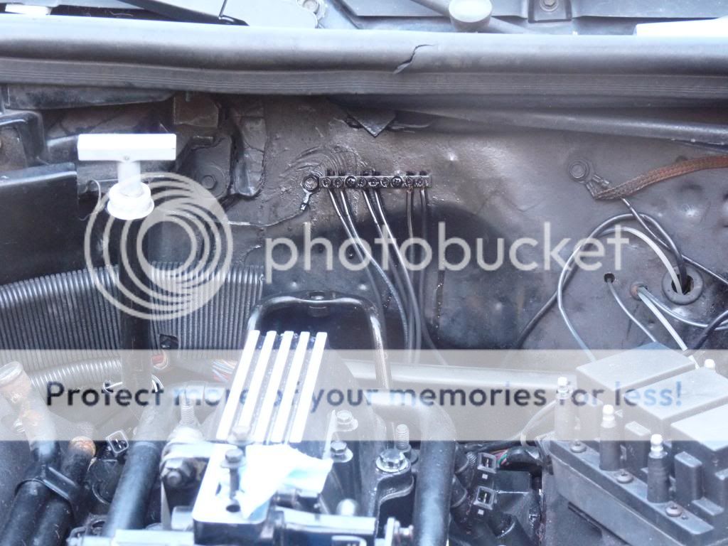
Consider how the factory grounds were designed. There were seven ground wires attached to four ring terminals which broke out of the harness with short pigtails, then attached to two of the bolts in the rear passenger side of the engine. They used the transmission bolts to secure them.

The brass ring terminals used were the type with floating shakeproof serrations, and they also tinned the copper wire (some were fully soldered). NOTE: It was common practice to "tin" the bare copper factory wire prior to staking the terminal, as the oxygen in the air slowly tarnishes and corrodes bare copper, causing resistance in the connection. Tin plating the exposed wire slows the process considerably. Today, oxygen-free copper conductors are improved and less prone to oxidation although eventually, mother nature gets her way.

The engine block is an ideal common ground being a mass of steel and iron. There is a short 10 gage pigtail from the battery negative to the inner fender well, completing the body ground. The 4 gage negative battery cable attaches to the engine block, through the turbo support bracket - revealing the biggest fault in the factory setup.

The factory engineers didn't consider the vibration the turbos exhibit, which eventually shakes the turbo bracket bolt loose ("bad ground"). Another anomaly the factory engineers didn't pick up on is the result of out-of-the-ordinary torque the turbo engine made, causing the transmission bolts with the soft brass ring terminals, serving as lock washers, to slowly loosen (steel lock washers are much less prone to loosening under excessive torque). Once the bolts loosen, it loses it's ground, and since electronics grounds share terminals, a "sensor loop" condition exists, where the sensors malfunction by sharing common negative connections without the necessary grounding. Try it yourself; disconnect one of the ring terminals and remove it from the bolt...multiple fault codes suddenly appear.

But, giving the engineers credit where credit is due, they also didn't realize that our cars would become "cult" cars, and would be hitting the 25 year mark, racing all the way, with many more years to come. We'll cut 'em some slack there.

So, the fix is to relocate the grounds to an area that isn't directly affected by engine flex. Use a larger flexible conductor and attach it to its own bolt (the rear intake bolt is sufficient as well). Add an additional connection from there to the body sheet metal and you have effectively improved the grounds. This separate ground stud now becomes "ground-zero" and can be used for your battery negative attachment as well, especially if you have located the battery in the rear of the car.

Years ago, I had identified a potential ground problem in the OEM engine harness. There are several internal splices within the harness that encompass the electronics grounds, and they all have the potential to fail.

Now for the shameless plug...The fix was incorporated into every harness Caspers builds: Each ground is run individually to its location, eliminating the internal splices. There are now fourteen individual electronics ground wires instead of the usual six, and they're much longer (built-in ground relocation).
 
Most of those grounds are for sensors on the motor. IMO they should stay there. The rear intake bolts are an alternative location that does not require cutting or extending the wires.

Shaun, make sure you have a good link from that junction back to the engine block.
 
Most of those grounds are for sensors on the motor. IMO they should stay there. The rear intake bolts are an alternative location that does not require cutting or extending the wires.

Shaun, make sure you have a good link from that junction back to the engine block.

I have 2 #10 wires running back to the 2 bolts for the coil pack stand.

Shaun
 
Next time I see you I'll get a piece of sheet metal & attach a #16 gauge wire. The I'll apply 1 leg of 3 phase with a center phase ground with 208 going thru it & see how well that metal panel conducts electricity. :biggrin:
I know apples & oranges AC is different then DC.

I agree that the best conductor for our vehicle is copper. Even on the body's copper ground strap it should have had it's own bolt to the block. Not one inteneded to secure a trans to the block. Who's Idea was it to hide the grounds behind the passenger head any way?

We have one of our questions for the T-party:biggrin:
 
I took this idea a little further. I used a 5 hole grounding bar mounted behind the coil pack, ran #6 stranded wire from the back of each head to the bar, one to the bottom of the coil pack mount, bolted all of the factory ground wires together with another #6 to go to the firewall, one from the ground bar to the firewall and one from the ground bar along the side of the intake down to the front of the head where the battery ground goes. Looks very clean. Pics are in my gallery.

http://www.turbobuick.com/forums/members/phoneguy-albums-grounding-bar-6-awg-stranded-wire.html


Bryan
 
I lengthened all the leads and used the stud method mentioned above in place of one of the intake bolts in the back by the trans dip stick. From the stud I also ran a ground to the coil pack and one directly to the battery using a 12 gauge wire. The setup is pretty much invisible. No weird issues. Car runs very clean at 6000+ rpm...no hiccups at all.
 
Top